Causes & Solutions of Short Shots in Injection Molding

Views: 6 Author: Site Editor Publish Time: Origin: Site
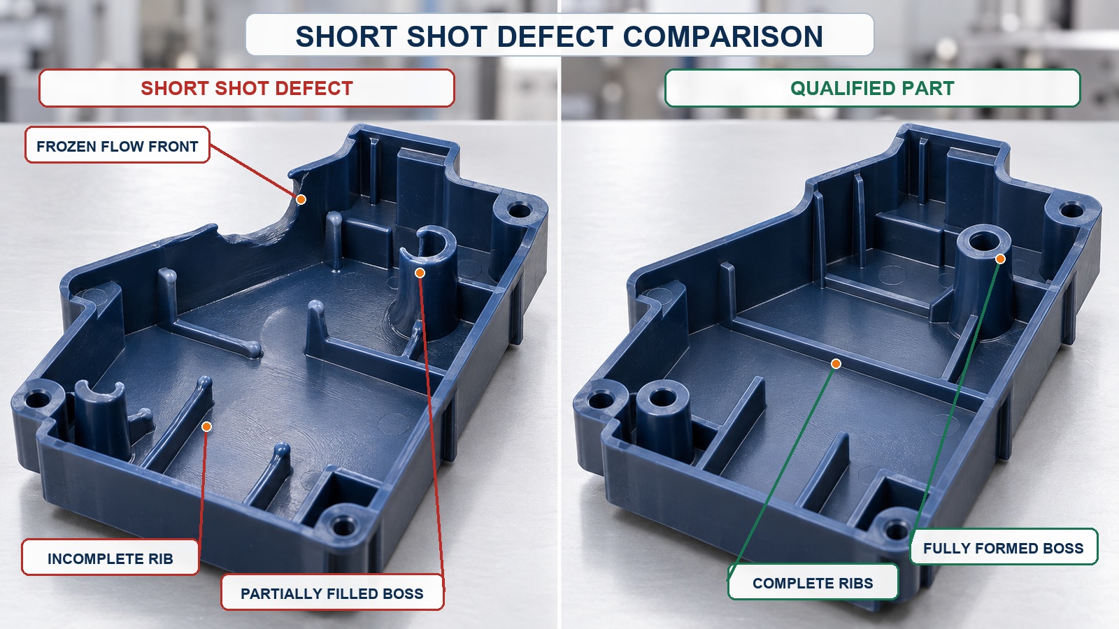
short shot is a typical defect in injection molding. It occurs when molten plastic fails to fully fill the mold cavity during the filling phase, resulting in incomplete parts with missing material at edges, thin-wall sections and other features. Distinguished from burns, sink marks and voids, its defining characteristic is incomplete cavity filling. It most frequently appears on thin walls, narrow runners, far-end ribs and small screw bosses.
Short shots directly lead to rejected parts and disrupt production cycles. Many on-site engineers tend to simply boost injection pressure, speed and barrel temperature to tackle this issue. Blind parameter adjustment often triggers secondary defects such as flash, burning, material degradation and high internal stress. Root causes fall into four categories: raw material, mold design, molding process and machine condition. Systematic troubleshooting is required instead of only raising pressure. Drawing on our experience in mold development and production trial runs, this article outlines root causes, recommended troubleshooting sequences and standardized corrective measures, helping engineers and procurement teams quickly diagnose problems during sampling and mass production.

I. What Is a Short Shot and Its Typical Signs

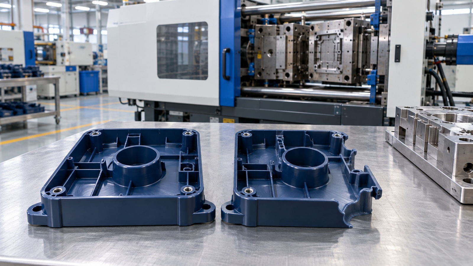
A short shot happens when the melt flow front stops prematurely before reaching the far end of the cavity, leaving localized material shortage. High-risk locations include thin-wall zones, long thin reinforcing ribs, small screw bosses, areas far from the gate and rib intersection zones.
Common symptoms:
  1. Incomplete outlines with missing material at edges and rib tips;
  2. Relatively clean fracture surfaces without obvious burning or blackening (to differentiate from burn marks);
  3. Intermittent success and failure under identical settings (unstable short shot);
  4. Parts can be fully filled after pressure increase, accompanied by flash and poor weld lines.
Key distinction: Short shot ≠ Sink mark . A sink mark forms after full cavity filling as plastic shrinks during cooling. A short shot means the cavity was never completely filled in the first place.

II. Main Causes of Short Shots

2.1 Mold Design Issues (Fundamental, Hard to resolve only by parameter tuning)

  1. Undersized gates and runners Small cross-sections of runners, pinpoint gates and film gates create high flow resistance. The melt loses pressure before filling the cavity. This risk rises sharply for high-viscosity materials and long-flow-path parts.
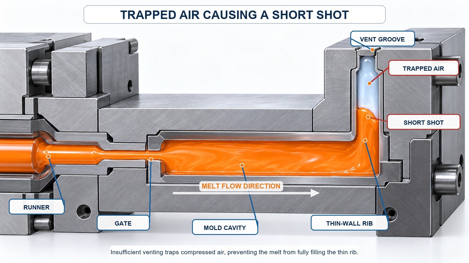
  2. Poor venting (very common) Trapped air inside the cavity cannot escape timely and gets blocked by incoming molten plastic. The resulting backpressure blocks the melt front, known as air trapping. Air-trap induced short shots often occur on thin walls, closed deep ribs and weld line locations. In many cases, parts still cannot fill even with higher pressure due to blocked vents.
  3. Excessively thin wall thickness and long flow path When the flow-length-to-thickness ratio exceeds the acceptable limit, plastic cools rapidly during flow, viscosity rises and fluidity drops. The melt solidifies before reaching the cavity end.
  4. Flow obstruction from draft and geometry Narrow gaps and deep narrow slots greatly increase flow resistance. Sharp corners and tight clearances in the cavity accelerate melt cooling and freezing.
  5. Low mold temperature A cold mold surface causes the melt to quickly form a solidified skin upon contact. This narrows the flow channel and reduces melt fluidity rapidly.

2.2 Raw Material Factors

  1. Insufficient material flowability: Within the same resin family, grades with low Melt Index (MI) show poor flow and are prone to short shots on long-flow thin-wall components.
  2. Inadequate material drying: Moisture vaporizes at high temperature, forming bubbles that obstruct flow and trigger material degradation with increased viscosity.
  3. High regrind ratio and degraded regrind: Multiple recycling breaks polymer chains and depletes additives, which reduces flow performance.
  4. Contamination and material mixing; foreign debris clogs the nozzle and screen pack.

2.3 Injection Molding Parameters (First items to adjust on the shop floor)

  1. Insufficient injection pressure: Cannot overcome flow resistance in runners and cavities.
  2. Slow injection speed: Extends filling time, the melt cools along the flow path and solidifies early at the flow front.
  3. Low barrel / nozzle temperature: Incomplete plastic melting leads to high viscosity and poor flow; excessive temperature causes degradation and abnormal viscosity.
  4. Insufficient injection stroke and melt volume: Short screw recovery produces inadequate melt for cavity filling.
  5. Early V/P switchover: Packing phase activates before the cavity is fully filled, terminating the filling stage.
  6. Low backpressure leads to uneven plastication and inconsistent melt density, resulting in intermittent short shots.

2.4 Hidden Machine Malfunctions (Easily overlooked)

  1. Clogged nozzle, worn nozzle or restricted nozzle flow.
  2. Worn screw and barrel cause melt slippage and insufficient actual shot volume.
  3. Inadequate hydraulic / servo output, indicated by nominal high pressure with low effective delivered pressure.
  4. Worn check ring with poor sealing allows melt backflow during injection, losing effective shot volume.

III. Standard Troubleshooting Sequence (From simple, low-cost checks to complex fixes)

Follow this sequence during on-site trials to avoid unnecessary mold modifications:
  1. Verify sufficient shot size and injection stroke setting.
  2. Check raw material: resin grade, melt index, drying condition and regrind percentage.
  3. Perform minor incremental adjustments to barrel temperature, mold temperature, injection pressure and speed.
  4. Examine the missing-material location to identify air trapping: whether the defect lies at far ends, rib junctions or non-vented zones.
  5. Inspect nozzle and screen pack for blockage; confirm proper sealing of the screw check ring.
  6. If parameter adjustments fail, evaluate mold modifications: enlarge gates/runners, add or widen vents, optimize wall thickness and reposition gates.

IV. Targeted Solutions

✅ Process Optimization (First priority, no mold changes required)

  1. Raise injection pressure and speed: boost filling driving force, shorten filling time and reduce premature cooling. Adjust in gradual steps instead of setting to maximum at once.
  2. Moderately increase barrel and nozzle temperature to improve melt flowability. Do not exceed the material supplier’s recommended upper temperature limit to avoid degradation.
  3. Increase mold temperature to slow skin formation on the melt surface and extend the available filling window.
  4. Increase screw recovery stroke to secure adequate melt reserve. Delay the V/P switch point to ensure full filling before packing starts.
  5. Raise backpressure appropriately to improve plastication uniformity, stabilize melt density and eliminate intermittent short shots.
  6. Raw material control: switch to higher-MI grades, reduce regrind percentage, dry resin per specification and remove foreign contaminants from the barrel.

✅ Mold Optimization (Adopted once process limits are reached)

  1. Improve venting: add vent slots at short-shot terminals and weld lines with properly controlled vent depth to release trapped cavity air.
  2. Enlarge gate / runner cross-section or relocate gates to shorten flow length and reduce flow-length-to-thickness ratio. Preferably position gates close to thin walls and far-end short-shot areas.
  3. DFM optimization of part design: increase wall thickness where feasible; add radii to long thin ribs to lower flow resistance.
  4. Optimize cooling circuits: add cooling channels near defective zones for balanced mold temperature and prevent localized overcooling.
  5. Polish runners and cavity surfaces to reduce frictional flow resistance.

✅ Machine Maintenance (When parameters and molds are verified sound but defects persist)

  1. Disassemble and clean the nozzle, replace screen packs and check for cold slug blockage.
  2. Inspect check-ring sealing performance and replace worn components if sealing fails.
  3. Calibrate machine pressure output to rule out pressure reading deviation and servo faults.
  4. Inspect screw and barrel wear. Severe wear causes melt slippage and unstable shot delivery.

V. Critical Reminders for Process Tuning

  1. Do not rely solely on unlimited pressure and speed increase: this frequently leads to flash, mold parting, high residual stress and burning.
  2. Distinguish air-trap short shots from flowability short shots: air trapping often cannot be solved simply by higher pressure and venting should be prioritized.
  3. Intermittent short shots are most commonly caused by unstable plastication, faulty check-ring sealing or poor drying.
  4. Calculate flow-length-to-thickness ratio during early DFM reviews to mitigate short-shot risks from thin-wall long-flow geometry.

Conclusion

Fundamentally, a short shot occurs when molten plastic lacks sufficient flow capacity to overcome cavity resistance and complete filling. It is a combined result of flow resistance, heat loss, trapped air and insufficient melt supply. The recommended improvement workflow is: raw material & process first, then machine inspection, and mold modification last , to avoid unnecessary mold rework costs. Early-stage DFM analysis with well-controlled wall thickness, flow ratio, gate layout and vent design is the most economical preventive measure, cutting trial cycles and raising mass-production yield.
×

Inquire

*Name
*Email
Company Name
Tel
*Message