This comprehensive guide is intended for engineers, product designers, procurement managers and decision makers who require a deep technical reference on injection moulds and injection moulding. The document covers the fundamentals of injection moulding, mould types and special variants, materials and steel grades, detailed design recommendations, simulation and validation practices, process parameters, defect causes and fixes, inspection methods, industry applications, cost and lead time drivers, and practical advice on selecting a reliable mould manufacturer. It also integrates the capabilities and service offerings of our company so you can see how a full service mould partner supports product development and production.
Injection moulds are precision tools that define the geometry, surface finish and functionality of plastic parts produced by injection moulding machines. After the initial investment in tooling, injection moulding enables high volume production with consistent part quality, repeatable dimensional accuracy and efficient per unit cost. Injection moulds are central to a wide set of industries including automotive, consumer electronics, medical devices, water treatment equipment, household appliances, security equipment and industrial components.
Well designed and manufactured moulds reduce scrap, shorten cycle times and enable complex multi material and multi color parts. Poorly designed moulds increase trial cycles, cause production defects and create hidden costs in rework and warranty. Investment in engineering, simulation, quality control and manufacturing capability is therefore crucial for successful projects.
Our company specializes in a broad portfolio of tooling and plastic component services. Our capabilities include injection moulds, precision moulds, big moulds, auto unscrewing moulds, double color two shot moulds also known as K2 moulds, metal insert moulding, injection molding parts, die casting parts, CNC machined parts and a wide range of end use parts including auto parts, electronic parts, security parts, household parts, industry parts, medical parts and water treatment parts. We provide turnkey solutions that span design, simulation, machining, assembly and trial runs. Our objective is to provide consistent technical excellence, traceable materials and strong after sales support.
When you engage with us we offer design for manufacturability feedback, materials and steel grade recommendations, finite element analysis and mouldflow simulation for flow and warpage prediction, precision machining and EDM, inspection with coordinate measuring machines, trial moulding, and structured handover documentation including maintenance manuals and spare parts recommendations.
The injection moulding process converts plastic resin pellets into finished parts through a cycle of plasticizing, injection, packing, cooling and ejection. The core steps are plasticizing the resin in the injection barrel, injecting the molten polymer into the mould cavity via the sprue and runner system, holding pressure to compensate for material shrinkage, cooling the part until it solidifies and then opening the mould and ejecting the part. Each step interacts with mould design, material selection and machine settings.
Cycle time equals injection time plus packing time plus cooling time plus ejection and handling time. Cooling time is typically the largest portion of cycle time for many parts. Optimized cooling reduces cycle time and improves dimensional stability but must be balanced against thermal gradients and residual stress. Part design, wall thickness, gate location and mould thermal control are primary factors in determining cycle time and part quality.
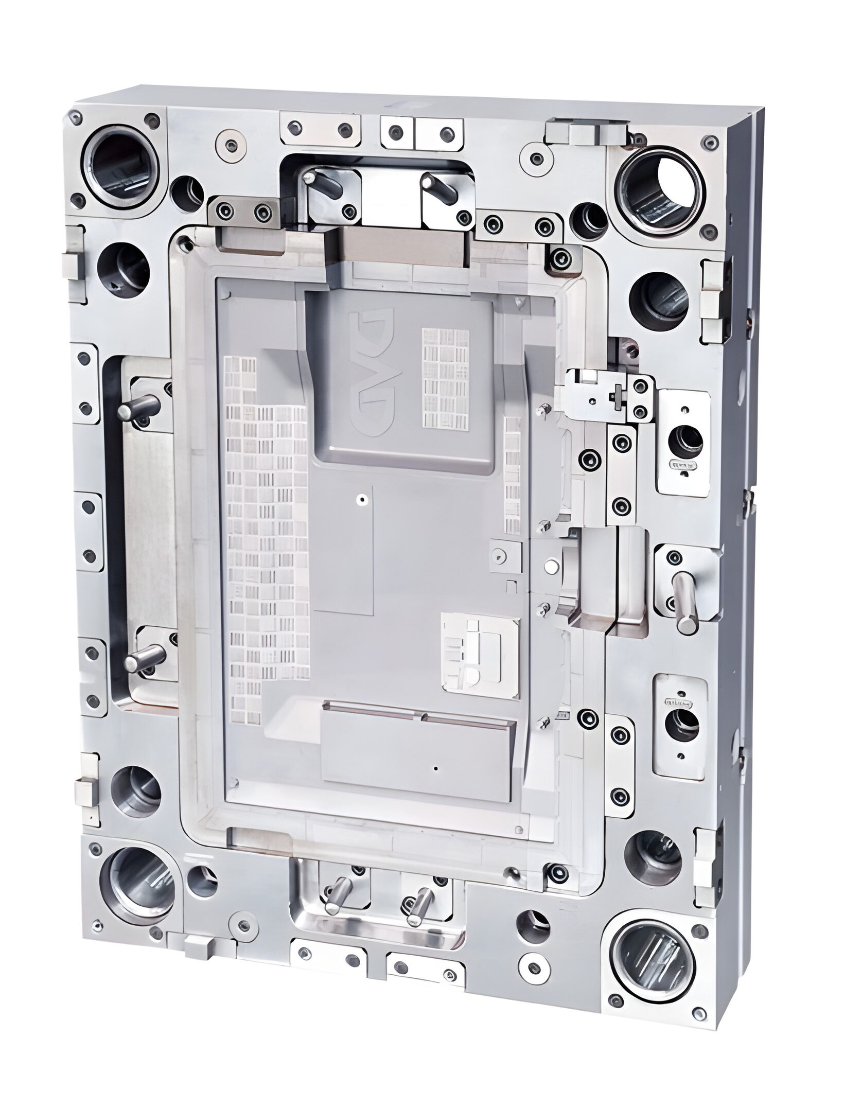
A modern injection mould is a complex assembly. Core components include cavity and core inserts, parting surfaces, sprue, runners, gates, cold or hot runner systems, ejector pins and plates, guide pillars, return pins, cooling channels and thermostatic circuits, venting channels, sliders and lifters for undercuts, unscrewing mechanisms for threaded features, and the mould base. The selection and configuration of these components is determined by part geometry, material properties and production volume.
Cooling circuits must be designed to achieve thermal balance. Poor cooling layouts lead to warpage and long cycle times. Venting must allow trapped air to escape at flow fronts without permitting plastic to flash. Gate design influences flow patterns and weld line locations. Ejection systems must remove parts without distortion or scuffing. Additional mechanisms such as slides or unscrewing assemblies increase complexity and maintenance requirements but are necessary for certain part features.
Injection moulds come in many forms. Choosing the correct mould type for an application is key to product performance and manufacturability.
Precision moulds are engineered for extremely tight dimensional tolerances and high surface quality. These moulds are used for connectors, medical devices, optical components and parts with micro features. Precision moulds often employ high grade steel, careful EDM finishing and mirror polishing where required.
Large or big moulds are used for sizable parts such as appliance housings, water treatment components and large industrial enclosures. Big moulds require robust mould bases, heavy machining, and special handling and storage provisions. Thermal management across large cavities is a primary engineering challenge.
Auto unscrewing moulds incorporate mechanisms that rotate an internal core or a part feature to release threads during ejection. These systems can be mechanical cam driven, hydraulic or servo controlled. They are essential for molded parts with integrated helical threads where manual disassembly is impractical.
Two shot or double color moulds combine two materials or two colors into a single molded assembly within one moulding cycle. These systems can use either rotary or linear indexing of the mould or use multi shot injection units. Two shot moulds enable overmolding of soft touch materials on rigid substrates, color accents and consolidated assemblies that otherwise would require assembly operations.
Insert moulds integrate metal or other inserts into the plastic part during molding. Inserts can be threaded nuts, bushings, terminals or functional metal components. Insert moulding reduces assembly operations and improves strength in combined metal plastic joints. Proper insert placement and fixturing during injection are critical to prevent displacement and to ensure consistent overmolding.
Other variations include family moulds which produce several different parts in the same cycle, multi cavity moulds which increase throughput by producing multiple identical parts per cycle, hot runner and cold runner systems, gas assist moulds which reduce sink in thick sections, and moulds with side actions or lifters to form complex undercuts.
Choosing the correct material for the part and the correct steel grade for the mould are both key decisions. For molded parts common thermoplastics include polypropylene, polyethylene, acrylonitrile butadiene styrene, polycarbonate, polyamide also referred to as nylon, acetal also known as POM, and high performance polymers such as PEEK and LCP. Each polymer has distinct properties in terms of melt flow, shrinkage, moisture sensitivity, thermal properties, mechanical strength and chemical resistance.
Material selection must consider the part operating environment, required mechanical performance, surface finish requirements and compatibility with downstream processes such as plating or painting. Filled grades containing glass fiber or mineral fillers alter flow behavior and increase abrasion on the mould. These materials usually require hardened sections or special coatings on the mould to reduce wear.
For tooling steels the choice depends on expected production volume, the abrasive nature of the chosen resin and the required surface finish. Pre hardened steels such as P20 are common for prototype and low volume production. Through hardened or hot work steels such as H13 provide higher thermal fatigue resistance and wear life for medium to high volume production. Stainless and corrosion resistant steels such as S136 and NAK80 are chosen for aesthetic and food or medical related applications because they polish well and resist corrosion. The mould steel selection must balance cost, machinability and expected service life.
Commonly used steel grades include P20, 718 and similar pre hardened grades, H13, S136, NAK80 and other specialty steels. Each grade has different hardness ranges, polishability, thermal conductivity and toughness characteristics. Heat treatment procedures such as hardening and tempering or nitriding must be carefully controlled to achieve the specified hardness while minimizing distortion.
For high volume production using abrasive resins or filled materials choose higher wear resistant and through hardened steels with appropriate surface treatments. For cosmetic or optical parts choose steels with high polishability and high corrosion resistance. Heat treatment vendors and machining shops must provide traceability and material certificates for critical applications. Mould maintenance schedules and spare part strategies should be planned based on the selected steel grade and expected shot count.
Design for manufacturability or DFM is a systematic approach to design parts and moulds so they are easier to manufacture, test and maintain. Key DFM recommendations for injection moulded parts include specifying uniform wall thickness, adding draft angles for ejection, minimizing deep bosses and thick sections, adding ribs for stiffness rather than thick walls, and selecting reasonable tolerances based on the function of the feature.
Gate selection must be informed by flow length, intended gate vestige, cosmetic requirements and weld line locations. Consider using hot runner systems to reduce gate vestiges and material waste when volumes justify the cost. Runner balancing must be examined for multi cavity and family moulds to ensure uniform filling and consistent part quality.
Cooling design is often the most impactful mould design element. Cooling circuits should aim for temperature balance across the cavity. Conformal cooling using additive manufactured inserts can provide improved thermal control for complex geometries. Baffles and bubblers are alternative techniques for improving cooling around deep pockets. Thermostatic control with temperature sensors in critical areas helps maintain consistent process conditions.
Venting should be provided in locations where flow fronts meet and where trapped air can cause voids or burns. Vents must be sized to remove air without creating visible flash. Ejection systems must be designed to support the part without distorting it during ejection. Consider ejector pin locations to avoid cosmetic areas and use stripper plates or sleeves for delicate parts.
Simulation tools such as Moldflow, Moldex3D and SolidWorks Plastics are widely used to predict fill patterns, warpage, cooling efficiency and weld line formation. Performing simulation early in the design phase reduces the number of physical trials and shortens development time. Typical simulation workflows include mesh generation from CAD, material definition and data input, gate position trials, flow simulation, pack and cool simulation and warpage prediction. The results guide gate design, runner sizing, cooling channel placement and sometimes require geometric changes to the part for manufacturability.
Simulation also supports virtual testing of process windows to establish robust operating parameters and to identify sensitivity of part quality to processing variations. Use simulation outputs to determine compensation factors for cavity machining if warpage cannot be eliminated via cooling or geometry changes. Simulation results should always be validated with trial moulding and correlated to physical measurements to refine the models.
Control of process parameters is essential for stable production. Core parameters include melt temperature, mould temperature, injection speed and pressure, pack pressure and time, screw speed and back pressure, and cooling time. Scientific molding methods use controlled experiments to map the process window, understand the sensitivity of part quality to parameter variations and define optimized set points. Typical steps include determining the optimal melt and mould temperature for the selected resin, establishing the fill profile, setting the packing profile to minimize voids, and then determining cooling time for acceptable part stiffness and dimensional stability.
Machine capability and repeatability are critical. Use properly calibrated temperature controllers for the barrel and mould, verify clamp force and ensure the injection unit can provide necessary speed and pressure. Implement SPC and periodic capability studies to maintain long term process control.
Understanding common defects and their root causes is essential to efficient production. The following lists typical issues with common corrective actions.
Short shot or incomplete fill is commonly caused by insufficient injection pressure or speed, overly long flow path, cold mould or inadequate gate size. Fixes include increasing injection pressure, increasing melt temperature, optimizing gate size or adding a gate, and using a hot runner if appropriate.
Warping and distortion result from uneven cooling or wall thickness variations. Mitigation approaches include redesigning for uniform wall thickness, improving cooling channel balance, modifying packing profiles and using simulation to predict and correct likely areas of deformation.
Sink marks appear in thick sections where localized material shrinkage causes surface depressions. Reduce wall thickness where practical, add ribs or supports to replace thick sections, increase packing or local cooling, or redesign the part to distribute material more uniformly.
Weld lines occur where two flow fronts meet and can weaken a part structurally or create cosmetic defects. Adjust gate locations, increase melt temperature and injection speed to reduce stiffness at the meeting point, or alter part geometry to move weld lines out of critical areas.
Flash is usually caused by parting line mismatches, excessive clamp load variations, worn mould surfaces or improper assembly. Correct by inspecting and reworking parting surfaces, adjusting clamp force, repairing worn components and ensuring proper mould maintenance routines.
Burn marks and overheating related discoloration result from trapped air, poor venting, high melt temperatures and shear heating. Improve venting, lower melt temperature, adjust injection speed and ensure resin quality and drying practices are correct.
Inspection should be integrated into the development and production lifecycle. Use coordinate measuring machines for first article inspection and periodic checks, optical measurement systems for surface quality and texture, and gauges for high throughput checks. Define critical dimensions and tolerances early and differentiate between functional tolerances that affect assembly or performance and cosmetic tolerances that affect appearance.
Establish acceptance criteria for first sampling runs, use statistical process control for production monitoring and maintain traceability records for materials and heat treatment. For regulated products such as medical devices add validated inspection and documentation processes that comply with relevant standards. Maintain a master inspection plan that lists inspection methods, sample sizes and acceptance thresholds.
Quality management systems such as ISO 9001 provide a foundation for consistent manufacturing practices. For medical, food contact or safety related parts consider additional standards such as ISO 13485 for medical devices and compliance with material contact regulations. Ensure your mould supplier can provide material certificates, heat treatment documentation, calibration records for inspection equipment and documented procedures for corrective and preventive actions. Supplier audits and capability assessments are a prudent step for critical projects.
Major cost drivers in tooling include part complexity, the number of cavities, steel grade and block size, surface finish requirements, the presence of slides or unscrewing mechanisms, hot runner systems, the number of machining hours including EDM work and manual polishing, and the need for simulation and iterative trials. Lead time is affected by engineering design time, machine availability, heat treatment scheduling, polishing and finishing lead times and the complexity of trial and correction cycles.
For low volume parts consider prototype aluminium or softer steel tools to reduce cost and lead time. For high volume production, invest in hardened steel tooling that withstands higher shot counts and abrasive materials. Plan for upfront investment in simulation and DFM to reduce iterations during trial moulding and to shorten time to production readiness.
Injection moulds are used across the automotive industry for interior and exterior components, in electronics for housings and connectors, in medical devices for critical precision components, in household appliances for panels and controls, in water treatment for housings and valves, and in security equipment for casings and sensor integrities.
Case Example Summary 1: For an automotive connector housing, a precision mould using a pre hardened steel insert for contact areas combined with a hot runner system reduced gate vestige and improved cosmetic appearance. Moldflow analysis was used to determine gate locations and cooling design which reduced warpage and resulted in consistent fit with mating parts.
Case Example Summary 2: For a medical instrument casing requiring optical clarity and mirror surfaces, a corrosion resistant steel grade was chosen. The mould was polished to optical finish and validated under controlled conditions. First article inspection used CMM and optical comparators and the mould delivered thousands of acceptable parts per month with low reject rates.
Selecting the right manufacturing partner involves evaluating technical capabilities, equipment, past project experience, quality systems, supply chain stability and after sales support. Key questions to ask include whether the supplier has in house CNC milling capability, EDM and wire EDM for complex cavities, an experienced design team that uses CAE tools, and a structured approach to trial moulding and FAI. Ask for documented references for projects similar to your part in size, tolerance and production volume.
Confirm that the supplier can provide material certification for steels, evidence of heat treatment quality, inspection capabilities including CMM, and a traceable quality system with documented procedures. Evaluate the supplier's ability to provide spare parts, maintenance plans and refurbishment services. Protect your intellectual property by using a mutually agreeable non disclosure agreement and clear contractual ownership of drawings and moulds.
Before finalizing a tooling purchase decision confirm the following items. Provide clear 3D CAD files in STEP or IGES format and 2D drawings with critical dimensions and tolerances. State the intended resin material and any filled variants, expected annual volume and target cycle time. Clarify required surface finishes and any regulatory or certification needs. Ask for a proposed gate plan, cavity count recommendation, expected mould life and warranty terms. Request documentation on material traceability for steel and heat treatment. Agree on acceptance criteria for first article inspection and on the number of trial iterations included in the contract. Confirm spare parts provision and the expected lead time for repairs and refurbishment.
At project completion provide a comprehensive handover package that includes mould drawings, heat treatment records, material certificates, control plans, a maintenance manual with recommended inspection intervals and spare parts list. Training for the production team on mould handling, cleaning and maintenance procedures minimizes downtime and extends mould life. Implement preventative maintenance practices including scheduled inspections of slides, ejectors and cooling channels and maintain a log of shots and any maintenance activities.
Sustainability considerations include minimizing material waste through efficient runner design and hot runner systems, using recycled or bio based resins where feasible, optimizing cycle times to reduce energy consumption and selecting steel grades with longer service life. Consider lifecycle impacts when choosing materials and processes. Implementing process monitoring and predictive maintenance reduces scrap and extends mould lifetime which is positive for environmental footprint.
For a successful injection mould project invest time and resources in early DFM, simulation and prototype testing. Provide your mould partner with clear requirements and collaborate on gate location, cooling strategy and material selection. Prioritize suppliers who can demonstrate proven experience, traceable material and process control and a strong after sales support structure. For complex parts insist on CAE validation and a structured trial mould plan with clearly defined acceptance criteria.
If you would like our assistance we offer full service support from initial DFM review and simulation to mould manufacturing, trial runs, inspection and end to end project handover including maintenance documentation and spare parts supply. To start a quotation process please share your part 3D file in STEP format, specify the intended resin and expected annual volume plus any critical tolerances or surface finish requirements. We will perform a preliminary DFM review and provide a detailed tooling proposal and project timeline.
To request a quotation or a DFM review please email your 3D model and technical requirements to the contact address on your website or to the project email used in your procurement channel. Include the part name, material choice, expected annual volume, critical dimensions and a short description of the application and any regulatory standards that apply. We will acknowledge receipt, perform an initial feasibility review and propose next steps including recommended cavity count, steel grade and expected lead time.
Thank you for reviewing this technical guide. We hope it supports your decision making and makes the tooling and injection moulding process clearer and more predictable. Our team is ready to support your product development and production needs with proven technical capability and a structured quality approach.

RM1223, 12F, No.1, Fuji Bldg, No. 6018 Longgang RD. , Longgang Dist., Shenzhen,China.


Tel: 0086-755-89618186

Contact: Paul Hu 0086-18675501028


 LEAVE MESSAGE